Polyethylene liner motion in dual-mobility hip prostheses: static and dynamic radiostereometry in 16 patients 1 year after operation
Peter Bo JØRGENSEN 1, Bart L KAPTEIN 2, Kjeld SØBALLE 1,3, Stig S JAKOBSEN 3, and Maiken STILLING 1,3
1 AutoRSA Research Group, Orthopaedic Research Unit, Aarhus University Hospital, Aarhus, Denmark; 2 Biomechanics and Imaging Group, Department of Orthopaedics, Leiden University Medical Center, Leiden, The Netherlands; 3 Department of Orthopaedic Surgery, Aarhus University Hospital, Aarhus N, Denmark
Background and purpose — Dual-mobility hip arthroplasty utilizes a freely rotating polyethylene acetabular liner to protect against dislocation. As liner motion has not been confirmed in vivo, we undertook this using dynamic radiostereometry (RSA).
Patients and methods — 6 patients with Anatomical Dual Mobility acetabular components were included. Markers were implanted in the liners using a drill guide. Static RSA recordings and patient-reported outcome measures were obtained postoperatively and at 1-year follow-up. Dynamic RSA recordings were obtained at 1-year follow-up during passive hip movement: abduction/external rotation, adduction/internal rotation (modified FABER–FADIR), to end-range and at 45° hip flexion. Liner and neck movements were described as anteversion, inclination, and rotation.
Results — Liner movement during modified FABER–FADIR was detected in 12 of 16 patients. Median (range) absolute liner movements were: anteversion 10° (5–20), inclination 6° (2–12), and rotation 11° (5–48) relative to the cup. Median absolute change in the resulting liner/neck angle (small articulation) was 28° (12–46) and in liner/cup angle (larger articulation) was 6° (4–21). Static RSA showed changes in median liner anteversion from 7° (–12 to 23) postoperatively to 10° (–3 to 16) at 1-year follow-up and inclination from 42° (35–66) postoperatively to 59° (46–80) at 1-year follow-up. Liner/neck contact was associated with high initial liner anteversion (p = 0.01).
Interpretation — The polyethylene liner moves over time. 1 year after surgery the liner can move with or without liner/neck contact. The majority of movement is in the smaller articulation between head and liner.
Citation: Acta Orthopaedica 2022; 93: 375–381. DOI http://dx.doi.org/10.2340/17453674.2022.2253.
Copyright: © 2022 The Author(s). This is an Open Access article distributed under the terms of the Creative Commons Attribution-NonCommercial 4.0 International License (https://creativecommons.org/licenses/by-nc/4.0/), allowing third parties to copy and redistribute the material in any medium or format and to remix, transform, and build upon the material for non-commercial purposes, provided proper attribution to the original work.
Submitted: 2021-06-22. Accepted: 2022-02-08. Published: 2022-03-21.
Correspondence: pbjr@clin.au.dk
PBJ, KS, SSJ, and MS designed the study, SSJ operated on the patients, PBJ wrote the manuscript draft, BK and PBJ wrote the Python and Matlab programs, PBJ and BK performed the image analyses. All contributed to the data interpretation, and critical revision of the manuscript.
Acta thanks Leif Ryd for help with peer review of this study.
The dual mobility (DM) hip prosthesis is designed with a mobile polyethylene liner that acts as a spacer between the femoral head and the acetabular component. Theoretically, the DM liner moves when the neck is in contact with the rim of the liner, which increases the range of motion before impingement, but movement of the DM liner in vivo has not been investigated. The DM design has been shown to reduce the postoperative dislocation rate while providing better range of hip movement compared with conventional implants (1,2). Further, intraprosthetic dislocation has been associated with blocking of the liner movement (3).
Liner movement in DM hip prostheses has been investigated only experimentally or by scratch patterns on retrieved liners (4-6). Documentation of DM liner movement in vivo is challenging due to the radiolucency of the polyethylene liner and radiopacity of the acetabular cup and femoral head. Small tantalum markers have previously been used to mark and visualize polyethylene liners for measurement of liner wear in single-mobility hip prostheses using marker-based radiostereometry (RSA) (7,8). However, occlusion of markers in the polyethylene by overlapping cup and head poses a challenge with this method that typically depends on visual marker projections in both images of the RSA recording (7,9,10). Information on marker positions from several RSA recordings of the DM hip may be used to construct a patient-individual combined markers configuration (CMC) model, which partially overcomes problems with marker occlusion and makes dynamic RSA measurements feasible for evaluation of DM liner mobility in vivo (10).
We hypothesized that the DM liner would be mobile 1 year after operation. Therefore, we (1) evaluated whether liner movement occurred in DM cups 1 year after primary operation and (2) described the movement pattern and range of such movement.
Patients and method
Patients
We included 16 patients (9 female) with DM articulations from an ongoing randomized clinical trial, which compared 30 DM vs. 30 ceramic/ceramic articulations (Table 1). The patients’ median age was 62 years (41–69) and the indication for surgery was primary hip osteoarthritis. Exclusion criteria were: Preoperative T-score < –1 on DXA scan of the spine and dual hip, neuromuscular or vascular disease in the affected leg, metabolic bone disease, dementia, lack of Danish citizenship, or inability to comprehend the Danish language.
| Factor | Total (n = 16) | Liner/neck angle | |
| < 36.6° (n = 10) | ≥ 36.6° (n = 6) | ||
| Age | 62 (41–69) | 62 (43–68) | 59 (41–69) |
| Sex (female/male) | 9/7 | 5/5 | 4/2 |
| BMI | 27 (18–40) | 27 (18–33) | 23 (21–30) |
| Oxford hip score (0–48) | 27 (13–37) | 29 (18–34) | 28 (26–37) |
| Pain, rest (0–100) a | 24 (0–76) | 22 (0–76) | 26 (16–48) |
| Pain, active (0–100) a | 54 (21–93) | 60 (24–86) | 43 (21–74) |
| a Visual analogue scale. | |||
Implants
All patients were operated on through a posterolateral access, using size 46–56 Anatomic Dual Mobility (ADM) cup, size 3–9, Accolade II stem with neck angle 127° (n = 4) and 132° (n = 12), and X3 HXLPE liners (Stryker, Warsaw, Mazovia, Poland). Ceramic v40 femoral heads size 28 (BIOLOX delta, CeramTec) was used. All polyethylene liners were prepared with 12 1-mm tantalum markers (X-medics, Frederiksberg, Denmark) in the liner rim during surgery using a custom designed drill-guide. The markers were positioned in 4 groups of 3 markers, and each group had a unique pattern (Figure 1).
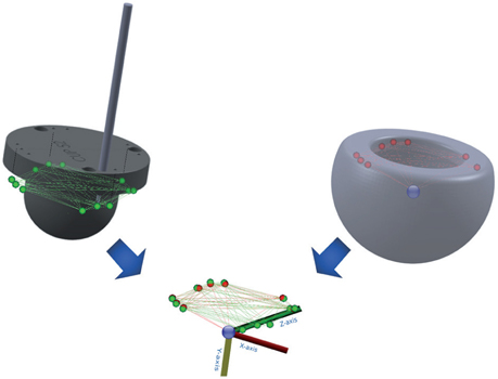
Figure 1. Hybrid model made by combining the theoretical (green) and measured (red) markers and head (blue). The 4 groups can be identified by 1 marker placed deeper in the PE (except for the far left group that is identified by all markers being at the same level).
RSA setup
The AdoraRSA Suite (Nordic X-ray Technique, Hasselager, Aarhus, Denmark) with 2 ceiling-mounted X-ray tubes angled at 40° to each other was used for RSA recordings. Static RSA images were recorded postoperatively and at 1-year follow-up with the patient supine, using a standard vertical tube setup, a standard calibration box (cb24, Medis Specials, Leiden, Netherlands) and digital static detectors (CXDI-70C, Canon, Tokyo, Japan). Dynamic RSA (dRSA) images were recorded at 1-year follow-up in a 45° cranial/caudal angle tube set-up. This recording position was chosen to balance optimal radiographic views and wide range of movement (Figure 2). A standard calibration box (cb14, Medis Specials, Leiden, Netherlands) and digital dynamic detectors (CXDI-50RF, Canon, Tokyo, Japan) were used. The image resolution was 2,688 x 2,208 pixels with 0.16 mm pixel spacing at 5 frames/second. The recorded hip motion was passive and applied by the same tester. The starting position was 45° hip flexion from which the hip was moved to end-range abduction/external rotation and end-range adduction/internal rotation—a modified flexion abduction external rotation/flexion adduction internal rotation (FABER–FADIR) motion—maintaining the 45° hip flexion (Figure 3). The hip motion was repeated for up to 2 cycles until the tester was confident that end range of hip motion was reached.
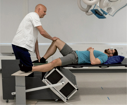
Figure 2. Dynamic radiostereometric recording. The patient was positioned at the end of the examination table with both feet on foot rests. The recorded hip was in 45° flexion and the foot remained fixed in this position.
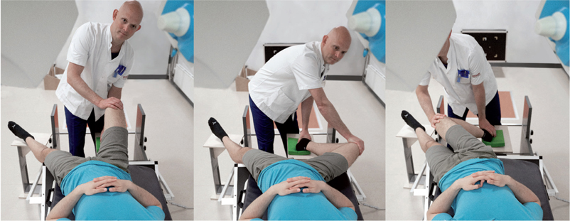
Figure 3. Hip movements during recording. From 45° flexion, the hip was rotated to end-range external rotation/abduction and end-range internal rotation/adduction (model image).
RSA analysis
The RSA recordings were analyzed using model-based RSA-software (mbRSA version 4.2, RSAcore, Leiden, The Netherlands). For the cup, which had a non-rotation symmetric shape, and the stem, standard projection matching techniques implemented in mbRSA were used (12). The markers inserted in the liner were registered in static and dynamic recordings as markers models (13). The femoral head was added as an extra marker to enable aligning of recordings with 2 overlapping markers. After aligning the models in mbRSA the marker positions from 4 to 7 RSA recordings were combined into a patient-specific combined markers configuration (CMC) model using MatLab (version 2019b, The MathWorks Inc, Natick, MA, USA). The local coordinate system of the CMC model was defined with the origin in the femoral head center and the y-axis (symmetry axis) perpendicular to the liner base plane fitted through the measured markers in the liner. Liner rotation about the y-axis was set to zero in the 1st dRSA recording. The CMC model was then applied to the dynamic recordings frame by frame in mbRSA, and matched to the femoral head and marker projections, to register liner movement. Finally, the motion patterns of the liner and stem components were extracted using a custom-made Python script (Python version 3.7, (14)).
Due to large variation in visible markers between the postoperative and 1-year static recordings, a hybrid model was constructed from the measured CMC model for best known marker positions and completed with the theoretical marker positions calculated from the CAD model of the drill guide. Combining these data sets resulted in a hybrid model including all 13 markers with the best accessible positions (Figure 1).
Liner orientation
Cup, liner, and stem orientations were calculated as inclination, anteversion, and rotation in a radiographic coordinate system (15) (Figure 4). The cup inclination and anteversion was measured in the static RSA recording relative to the calibration box. To adjust for patient movements during the recording, the dynamic recordings were aligned with the 1st frame and static recordings were aligned with the baseline recording, using the cup position as reference. Total liner inclination/anteversion/rotation was defined as the amount of change in inclination/anteversion/rotation throughout the modified FADIR–FABER hip motion. 24 dRSA frames in 2 patients (nos 4 and 9) with missing data for the liner due to soft tissue overlay were not included in the results or analysis. Liner movement was defined as change in orientation relative to the cup. Total liner movement was defined as the amount of movement throughout the modified FADIR–FABER hip motion. To remove noise and identify patients with liner movement a moving average filter of 5 datapoints was applied to the measured liner angles. Liners were defined as moving if filtered movement exceeded 5° in any angle. This ensured that liners with small amplitude of movement were included while maintaining a large margin for measurement error. For all other measurements and graphs of liner movements, the non-filtered data was used.
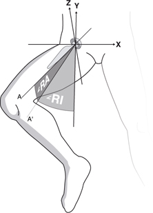
Figure 4. Radiographic inclination (RI) and radiographic anteversion (RA).
The liner/cup angle was defined as the angle between liner base plane normal vector and the cup base plane normal vector. The liner/neck angle was defined as the angle between the liner normal vector and the neck axis. Increasing liner/neck angle inferred smaller distance between the rim of the liner and the neck. Based on a phantom study, contact between liner and neck was expected at liner/neck angles = 36.6° (10).
Clinical outcome
The Oxford Hip Score (OHS) was obtained preoperatively and at 1-year follow-up, and was evaluated on a scale from 0 points (worst) to 48 (best) (16). Pain at rest and activity was recorded on a visual analogue scale (0–100) at baseline and 1-year follow-up.
Statistics
The dataset was dichotomized based on measured neck/liner angle below/above 36.6°. Data was evaluated for normal distribution using q-q plots. Student’s t-test was used for testing hypothesis with normally distributed variables and Wilcoxon’s rank sum was used for testing the hypothesis with variables that were not normally distributed. Liner orientation and patient-reported outcomes were presented using median (range). Correlations between liner movement, cup position, initial liner position, and stem movement were evaluated using scatter plots. The correlations were tested using simple linear regression and the residuals were evaluated using scatter and q-q plots. Statistical significance was assumed at p < 0.05 and 95% confidence interval (CI) was used. Statistical calculations were performed using Stata (Stata/IC 16.1, StataCorp, College Station, TX, USA).
Ethics, registration, funding, and potential conflicts of interest
This study was approved by the Central Denmark Ethics committee (1-10-72-343-14) and Danish Data protection Agency (1-10-72-343-14) and was registered in ClinicalTrials.gov (NCT02301182). All patients gave informed consent and the Helsinki II declaration was followed (11).
Stryker funded the study, but had no influence on the manuscript or publication. All authors declared no conflicts of interest.
Results
Dynamic RSA
The CMC models for the 16 patients consisted of median 8 (5–10) markers. All 6 liners that reached the 36.6° threshold for liner/neck contact moved more than 5° in inclination, anteversion, or rotation. 6 of the 10 liners that stayed below the 36.6° liner/neck angle also moved at least 5° in inclination, anteversion, or rotation in the filtered data. The remaining 4 liners moved less than 5° in all rotations measured on filtered data.
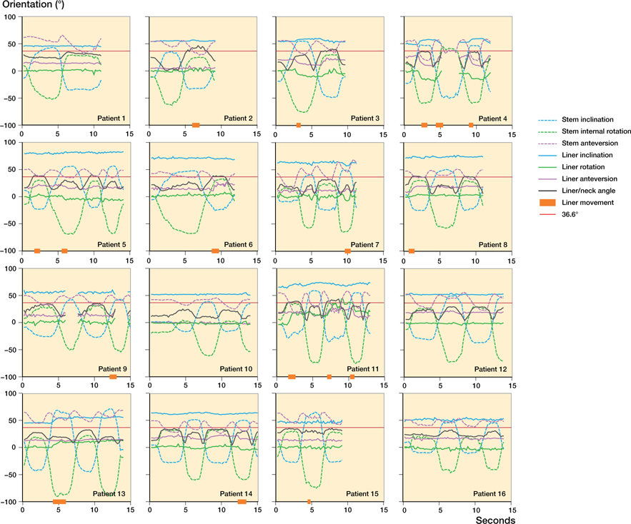
The liner movement showed a clear pattern, but the extent of movement varied greatly between patients. Liner anteversion and inclination occurred with end-range stem inclination/rotation (at 7 and 10 seconds, Figure 5). Liner rotation occurred in end-range inclination/rotation combined with stem anteversion movement (2 seconds, Figure 5).
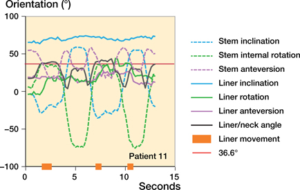
Figure 5. Example of stem and liner movement. For complete collection of graphs see Supplementary data.
Total liner anteversion correlated with the initial liner anteversion of the dynamic recording (slope 0.42, p = 0.04), and was most pronounced in the patients with liners moving beyond the liner/neck contact point (36.6° liner/neck angle) (p = 0.02). Total liner inclination correlated with total stem inclination movement (slope 0.11, p = 0.03) and was equally present in patients with liners moving below and beyond the liner/neck contact point (36.6° liner/neck angle). Total liner rotation was not correlated with specific stem movements and was equally distributed for liners moving beyond the liner/neck contact point (36.6° liner/neck angle).
The median total change in liner/neck angle was 28° (12–46) and larger than the median total change in liner/cup angle of 6° (4–21) (p < 0.001). This means that the smaller headliner articulation contributed with larger movement than the larger liner-cup.
Static RSA
For liner movement over time, 3 patients were excluded due to poor model representation in the postoperative RSA recording.
At 1-year follow-up, liner orientation showed substantial liner movement from postoperatively. Median absolute change was 11° (1–17) in anteversion, 14° (1–42) in inclination, and 104° (7–165) in rotation (Table 2). While the median anteversion did not change statistically significantly over time, the median inclination increased from 42° (35–66) to 59° (46–80) (p < 0.001) (Figure 6). At 1-year follow-up, all liners reached higher inclination angle than the cup (Figure 7, Table 3).
| Factor | Total (n = 16) | Liner/neck angle | p-value | |
| < 36.6° (n = 10) | ≥ 36.6° (n = 6) | |||
| Cup anteversion a | 23 (18–27) | 22 (16–27) | 24 (14–35) | 0.6 |
| Cup inclination a | 43 (40–46) | 43 (39–46) | 43 (35–50) | 1.0 |
| Initial liner anteversion a | 14 (11–18) | 14 (10–19) | 14 (8–20) | 0.9 |
| Initial liner inclination a | 57 (52–63) | 52 (47–57) | 66 (55–77) | 0.01 |
| Total liner anteversion b | 10 (5–20) | 7 (5–20) | 13 (10–20) | 0.02 |
| Total liner inclination b | 6 (2–12) | 8 (2–12) | 6 (3–11) | 0.8 |
| Total liner rotation b | 11 (5–48) | 11 (6–20) | 12 (5–48) | 0.7 |
| Total stem anteversion b | 25 (16–56) | 24 (16–56) | 27 (17–42) | 0.9 |
| Total stem inclination b | 79 (55–117) | 80 (55–117) | 78 (70–104) | 0.9 |
| Total stem rotation b | 97 (66–113) | 92 (66–113) | 100 (88–113) | 0.3 |
| Max liner/neck angle b | 35 (25–47) | 34 (25–36) | 41 (38–47) | < 0.01 |
| Total liner/neck angle b | 28 (12–46) | 25 (12–31) | 36 (27–46) | 0.01 |
| Total neck/cup angle b | 43 (25–70) | 37 (25–70) | 48 (36–68) | 0.2 |
| Total liner/cup angle b | 6 (4–21) | 5 (4–21) | 9 (5–15) | 0.1 |
| Oxford hip score angle b | 47 (18–48) | 46 (32–48) | 47 (18–48) | 0.5 |
| Pain decrease, rest a | 23 (12–34) | 26 (15–37) | 18 (−11–48) | 0.5 |
| Pain decrease, active a | 43 (24–63) | 48 (23–73) | 35 (−7–77) | 0.5 |
| a Values are mean° (95% CI) and p-value calculated with Student’s t-test b Values are median° (range) and p-value calculated with Wilcoxon rank sum test. |
||||
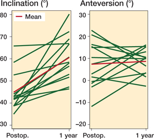
Figure 6. Line plot visualizing the change in liner orientation from postoperative static RSA recordings to follow-up after 1 year. There was a statistically significant increase in inclination, but no significant change in anteversion.
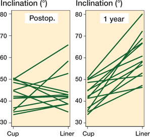
Figure 7. Parallel plot visualizing the cup/liner relationship postoperatively and at 1-year follow-up. After 1 year all liners showed more inclination than the cup.
Clinical outcomes
OHS increased 15 (CI 10–20) points from baseline to 1-year follow-up with no statistically significant difference between the groups (p = 0.6). Pain during rest and activity decreased mean 23 (CI 12–34) and 43 (CI 24–63) points with no statistically significant differences between groups (p = 0.5).
Discussion
The key finding of the study was that the polyethylene liners in dual-mobility hip prostheses move in vivo at 1-year follow-up, but with great variation between patients. In the large articulation, liner anteversion was initiated by contact with the neck whereas liner rotation and inclination were not associated with liner/neck contact.
Dynamic RSA
All 6 patients’ liners that reached the expected threshold for liner/neck contact showed liner movement of more than 5° (nos 2, 3, 5, 6, 8, 11); however, 6 liners that did not surpass the expected liner/neck contact angle also moved more than 5°. For 5 of the patients, the liner/neck angle continued to increase after the initial liner movement (nos 4, 7, 9, 13, 14). Therefore, these liners moved without direct liner/neck contact. 1 patient was just above the threshold for liner motion (5.4°) and showed no sign of liner movement (no. 16). It is therefore most likely that the recorded movement was due to noise (Figure 8, see Supplementary data).
The dual-mobility hip prosthesis has a large articulation between the liner and the cup and a small articulation between the liner and the femoral head. The observed relationship between liner/neck and liner/cup angles supports the view that most movement in the DM hip arthroplasty takes place in the small articulation between femoral head and liner, whereas movement in the large articulation between the liner and the cup is smaller in magnitude and stimulated in end-range hip movements. These findings support the biomechanical rationale behind the dualmobility cup (17).
During gait, the neck may come in contact with the liner as a result of the flexion/extension movement of the hip. In a phantom setup with loaded hip movements, Gao et al. (6) found that initial liner anteversion outside the range of +/- 20° resulted in liner/neck contact and liner movement during simulated gait. We found no association between initial liner anteversion and liner/neck contact. However, we did find an association between initial liner inclination and liner/neck contact. The difference in associations is likely because we studied a movement with more inclination and less anteversion.
Gao et al. (6) also found that inclination and anteversion of the cup had no influence on liner/neck contact. Likewise, we found no association between cup anteversion/inclination and liner/neck contact.
Static RSA
Liner orientation changed for all patients from baseline to 1-year follow-up, with large differences in the magnitude of change of orientation between patients.
At 1-year follow-up we found a median liner inclination of 59°, which was well above the median cup inclination of 42° at postoperative recording. If liners remain in a very high inclination, this could raise concern about uneven wear. Although patient activities before the RSA recording were not controlled, the high inclination of the liner may be explained by patients walking prior to RSA recording. In a phantom experiment with continuous gait cycles, Fabry et al. (5) found that liners moved from a neutral position towards inclination of 60° and anteversion of 24°. In contrast, the median anteversion of 10° in this study was somewhat smaller.
Measured, theoretical, or hybrid liner model
Measured models are constructed from actual marker projections. Marker projections occur even when the markers are misplaced. Markers can be misplaced for a number of reasons, including variation in equipment (drills and guides) and variation introduced when inserting markers (e.g., rotating the drill guide, or not obtaining the optimal depth of the marker). The greatest downside with measured models is that they require markers to be visible in both images of the RSA frame at some point. Therefore, it is very likely that some marker information never comes into play when using this method.
Theoretical models are constructed from expected marker positions and can provide a complete model based on the CAD drawings of the instrument used as the guide for marker insertion. The major downside of a theoretical model is that any deviation from the intended marker placement would result in errors and imprecision.
The hybrid model combines measured and theoretical marker positions and therefore receives strengths and weaknesses from both models. A hybrid model was chosen for analysis of the static RSA recordings because large and unknown liner movements over time required a complete model with ID of all marker groups. For the dynamic recordings a CMC model was chosen for its robustness, because there were smaller movements.
Liner/neck contact
The cut-off angle of 36.6° liner/neck angle appeared not to be consistent but varied between liners with a rather large range in maximal liner/neck angles over 36.6° (38–47). This could partly be explained by variation in the plane-fitting that is used to calculate the coordinate system of the CMC model and hence be a weakness due to the use of a measured model. Another reason could be variation of the opening angle and depth of the liners due to size differences and production tolerance.
Strengths and weaknesses
This is the 1st study to measure in vivo liner movement—dynamically and over time. We utilized a method for dynamic liner tracking that modelled the markers directly. This hybrid/CMC model RSA method is robust to occluded marker projections, or markers that have changed position from the originally intended position, and enabled markers that were only visible in 1 of the stereo images. Further, the use of marker models has a high accuracy with a relatively small number of markers (13).
The variation in maximum liner/neck angle was a drawback in this study because it indicates variation in the contact angle. Variation in contact angle could lead to misclassification of liner/neck contact for some patients and could affect the associations calculated. A better solution would have been to determine the individual contact angle. Unfortunately, this was not possible in our setup since we would need preoperative measurements of each implant. Another weakness of the study was that the recorded movement was not weightbearing. However, it did reflect everyday activities with risk of hip dislocation such as the patient reaching for the foot, i.e., to put on shoes or socks. The set-up and hip movement were chosen after many experiments aiming to keep the hip joint/prosthesis area within the field of recording, close to the detectors, and avoiding too much soft tissue overlay.
Conclusion
This is the 1st clinical study to show that dual mobility liners move in vivo. Movement occurred in 2 modes: (a) movement over time of all analyzed liners and (b) dynamic movement of some liners stimulated by end-range hip movement. Dynamic liner movement occurred with or without liner/neck contact. Movements presented with a similar pattern between patients but to a very different extent and the majority of movement occurred in the small articulation.
- Guyen O, Chen Q S, Bejui-Hugues J, Berry D J, An K N. Unconstrained tripolar hip implants: effect on hip stability. Clin Orthop Relat Res 2007; 455: 202-8. doi: 10.1097/01.blo.0000238796.59596.1f.
- McArthur B A, Nam D, Cross M B, Westrich G H, Sculco T P. Dual-mobility acetabular components in total hip arthroplasty. Am J Orthop (Belle Mead NJ) 2013; 42(10): 473-8.
- Philippot R, Boyer B, Farizon F. Intraprosthetic dislocation: a specific complication of the dual-mobility system. Clin Orthop Relat Res 2013; 471(3): 965-70. doi: 10.1007/s11999-012-2639-2.
- Grazioli A, Ek E T, Rudiger H A. Biomechanical concept and clinical outcome of dual mobility cups. Int Orthop 2012; 36(12): 2411-18. doi: 10.1007/s00264-012-1678-3. PubMed Central PMCID: PMC3508052
- Fabry C, Kaehler M, Herrmann S, Woernle C, Bader R. Dynamic behavior of tripolar hip endoprostheses under physiological conditions and their effect on stability. Med Eng Phys 2014; 36(1): 65-71. doi: 10.1016/j.medengphy.2013.09.007.
- Gao Y, Chen Z, Zhang Z, Chen S, Jin Z. Effect of inclination and anteversion angles on kinematics and contact mechanics of dual mobility hip implants. Clin Biomech (Bristol, Avon) 2018; 57: 48-55. doi: 10.1016/j. clinbiomech.2018.06.009.
- Nebergall A K, Rader K, Palm H, Malchau H, Greene M E. Precision of radiostereometric analysis (RSA) of acetabular cup stability and polyethylene wear improved by adding tantalum beads to the liner. Acta Orthop 2015; 86(5): 563-8. doi: 10.3109/17453674.2015.1054255. PubMed Central PMCID: PMC4564778
- Lindalen E, Nordsletten L, Röhrl S M. Segment choice and cup stability influence wear measurements using radiostereometric analysis: a radiostereometric study comparing wear measured by markers in the polyethylene with markers in the periacetabular bone. Clin Biomech (Bristol, Avon) 2012; 27(5): 511-14. doi: 10.1016/j.clinbiomech.2011.11.009.
- Garling E H, Kaptein B L, Geleijns K, Nelissen R G, Valstar E R. Marker configuration model-based roentgen fluoroscopic analysis. J Biomech 2005; 38(4): 893-901. doi: 10.1016/j.jbiomech.2004.04.026.
- Jørgensen P B, Kaptein B L, Søballe K, Jakobsen S S, Stilling M. Combined and hybrid marker models for radiostereometry assessment of polyethylene liner motion in dual mobility hip prosthesis: a proof-of-concept study. Eur Radiol Exp 2021; 5(1): 55. doi: 10.1186/s41747-021-00253-x.
- World Medical A. World Medical Association Declaration of Helsinki: ethical principles for medical research involving human subjects. JAMA 2013; 310(20): 2191-4. doi: 10.1001/jama.2013.281053.
- Kaptein B L, Valstar E R, Stoel B C, Rozing P M, Reiber J H C. A new model-based RSA method validated using CAD models and models from reversed engineering. J Biomech 2003; 36(6): 873-82. doi: 10.1016/s0021-9290(03)00002-2.
- Kaptein B L, Valstar E R, Stoel B C, Rozing P M, Reiber J H. A new type of model-based Roentgen stereophotogrammetric analysis for solving the occluded marker problem. J Biomech 2005; 38(11): 2330-4. doi: 10.1016/j.jbiomech.2004.09.018.
- Van Rossum G, Fred L. Python 3 reference manual. Scotts Valley, CA: CreateSpace; 2009.
- Murray D W. The definition and measurement of acetabular orientation. J Bone Joint Surg Br 1993; 75(2): 228-32. doi: 10.1302/0301-620X.75B2.8444942.
- Murray D W, Fitzpatrick R, Rogers K, Pandit H, Beard D J, Carr A J, et al. The use of the Oxford hip and knee scores. J Bone Joint Surg Br 2007; 89(8): 1010-14. doi: 10.1302/0301-620X.89B8.19424.
- Noyer D, Caton J H. Once upon a time.... Dual mobility: history. Int Orthop 2017; 41(3): 611-8. doi: 10.1007/s00264-016-3361-6.
